Architecture Overview
The ÆRIS is a web-based simulator of the RISC-V (RV32I) architecture, designed with a modular architecture that separates the graphical interface from the simulation logic.
The system is structured to divide responsibilities such as:
- assembly code analysis
- instruction assembly
- program execution
- simulated machine state updates
This separation makes the simulator easier to maintain, understand, and extend.
In general, the simulator is composed of two main blocks:
- Graphical Interface – responsible for user interaction
- Simulation Core – responsible for analyzing, assembling, and executing RISC-V code
Communication between these parts occurs through a central state object that holds all information about the current simulation.
Overall Architecture
Section titled “Overall Architecture”The ÆRIS architecture follows an organization inspired by Clean Architecture, separating the simulator logic into different layers.
The main layers are:
- Domain Layer - contains the core logic of the simulator and the processor model
- Application Layer – defines the system use cases
- Adapters Layer – integrates external services and communication with the interface
- Interface Layer – Angular components responsible for the graphical interface
This organization allows the simulation core to operate independently from the interface, simplifying maintenance and system evolution.
Simulation Core
Section titled “Simulation Core”The simulation core is responsible for processing and executing programs written in RISC-V assembly.
It is composed of three main components:
- Code Analyzer
- Assembler
- Processor
These components work sequentially to transform assembly code into executable instructions and simulate their execution.

Code Analyzer
Section titled “Code Analyzer”The Code Analyzer interprets the assembly code written by the user and prepares the necessary information for the assembly process.
Its responsibilities include:
- splitting the code into lines and instructions
- identifying
.textand.datasegments - expanding pseudo-instructions
- resolving labels
- building the symbol table
The result of this process is an intermediate representation of the program, which will be used by the assembler.

Assembler
Section titled “Assembler”The Assembler converts the intermediate program representation into RISC-V machine code.
Each instruction is analyzed to determine its opcode and format. The simulator supports the R, I, S, B, U, and J formats, which define how instruction fields are organized and encoded into 32-bit machine code.
Based on this information, the assembler generates the corresponding 32-bit binary instruction, which is then loaded into the simulated memory.

Processor
Section titled “Processor”The Processor is responsible for executing the instructions generated by the assembler.
It simulates the main components of a RISC-V processor, including:
- Register File – set of registers
- Program Counter (PC)
- Memory
- ALU (Arithmetic Logic Unit)
- Control Unit
- Immediate Generator

Simulation State
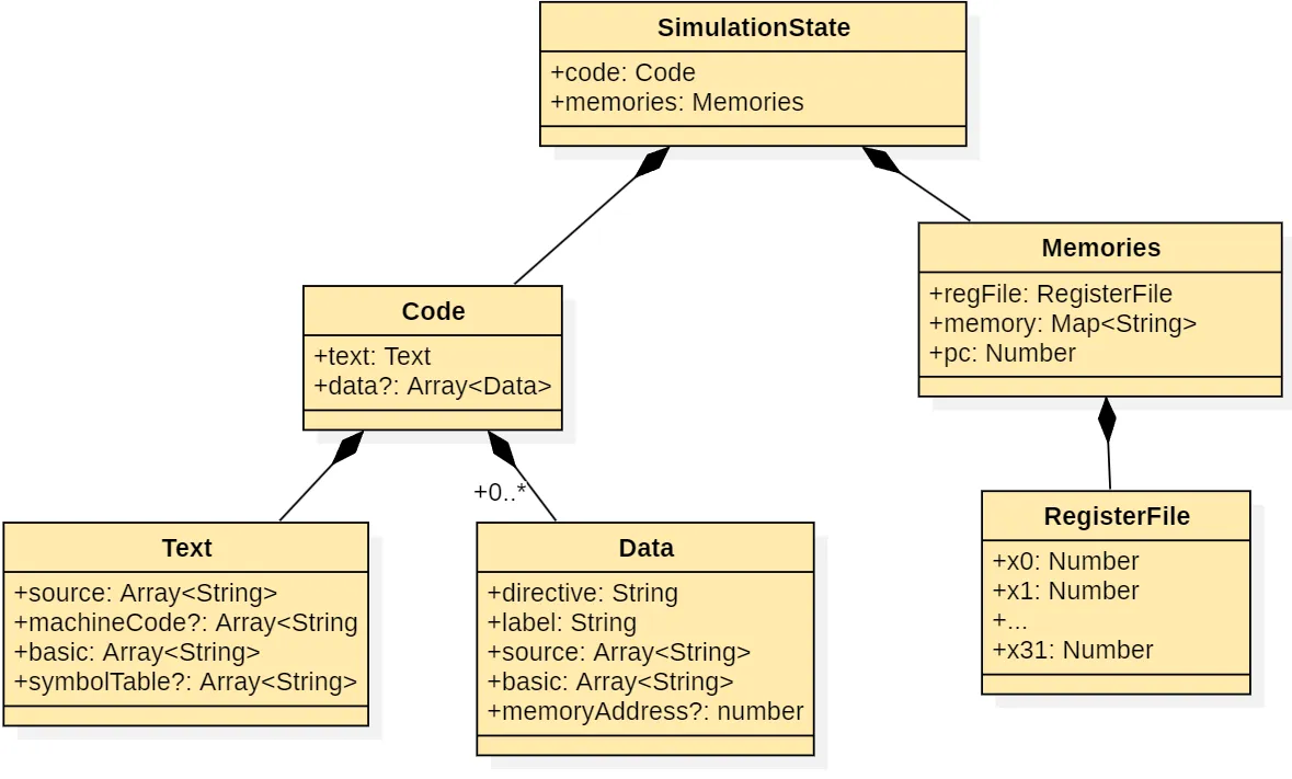
Section titled “Simulation State”All execution data is stored in a central object called SimulationState.
This object holds:
- program binary code
- program data
- symbol table
- memory contents
- register values
- current program counter value
The SimulationState acts as a bridge between the simulation core and the graphical interface, ensuring that any changes in the processor state are reflected in real time.
Graphical Interface
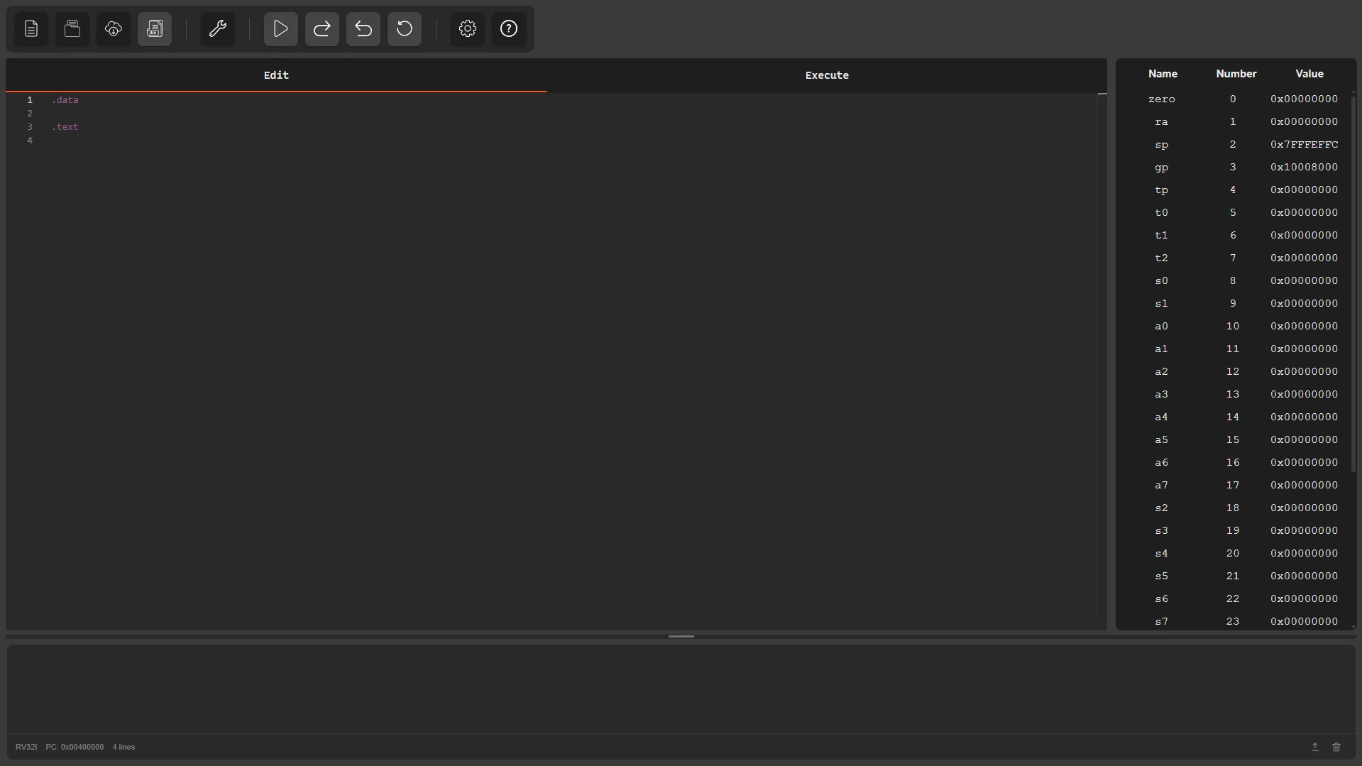
Section titled “Graphical Interface”The simulator interface is built using the Angular framework, following a component-based architecture.
The environment is organized into different panels, each responsible for displaying a specific part of the simulation state:
- Options Menu – provides main actions such as creating/opening files, assembling code, controlling execution, and accessing settings or help
- Editor Panel – allows writing and editing RISC-V assembly programs
- Execution Panel – displays assembled code and memory contents during execution
- Register Panel – shows the current state of processor registers
- Console – displays system messages, program output, and allows user input
These components interact directly with the central simulation state object, which keeps track of registers, memory, executed instructions, and other elements of the simulated processor.